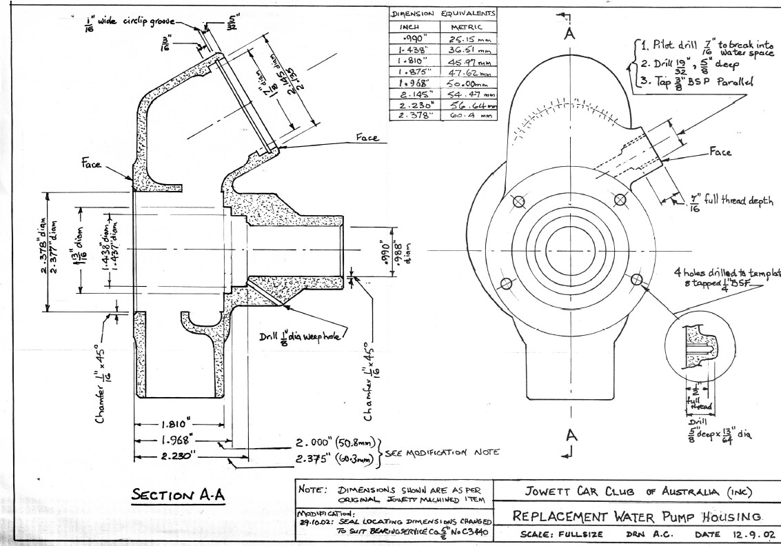
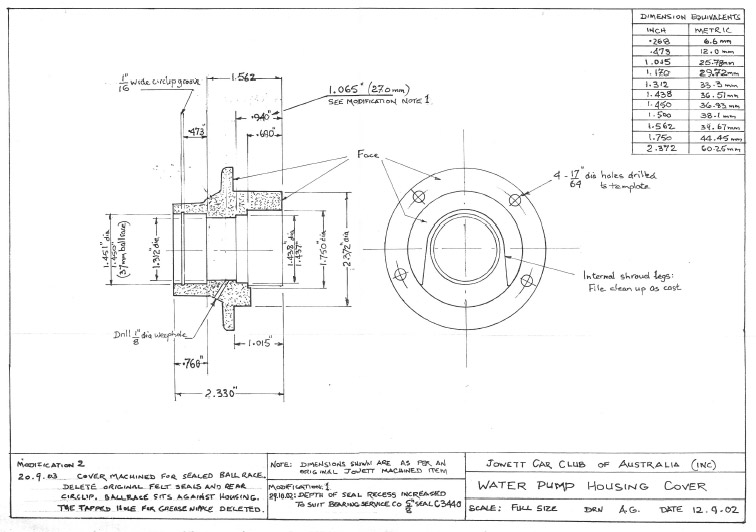
Tony beachcomber@iinet.net.au has some stunning modifications displayed here. First the water pump, then the main bearings, and the crankcase modification tool. Plus front (early) suspension, front hubs , crankcase tie-bolts, and problem with carbs.
By: Neil Moore UPDATED 2006.
EDITOR’s NOTE: This article originally appeared in “Flat—Four” June — November 1978. It has been updated for us by the author.
The subject of engine—bearing. life has interested me ever since I became the owner of a Javelin 28 years ago. As my knowledge of the motor grew it seemed the Javelin was plagued by bearing problems more or less from its beginning. The list of engineering changes show this with a number of modifications to improved bearing materials, stiffer con—rods and crankcase, and oil pump of increased delivery, less aeration combined with a non—draining filter housing. The crankshaft also came in for its share of problems and after some modifications to the original “Square” web including flame hardening of journals and increased radii in bearing journal corners, the “Oval” web was introduced about the beginning of 1954. The “Nitrided Oval” web shaft to increase resistance to metal fatigue and wear was introduced from 1958 on.
This gave a fairly satisfactory life of 50,000 to 80,000 miles between major overhauls if copper—lead bearings were used with the oval shaft, and Jowetts gained a fair reputation among the motoring public for speed rather than longevity.
However, in New Zealand it seems we had another problem with inferior bearings. These gave rise to shorter life engines and some unwarranted reputations. This was due to Bradford and Javelin big—end dimensions being the same, but the Bradford specification calling for white metal and the Javelin for copper—lead. However, for approximately 10 years, locally produced bearings were of one type, white metal for both and the problem was further compounded by producing white metal shells for the Javelin front and centre mains, (The rear is white metal with thrusts anyway as this is the only way it can be manufactured).
It must be borne in mind that this is ancient history (1950s—60s) and while the local manufacturer was mistaken in producing them anyway, it was a situation created by the very harsh import controls imposed by New Zealand governments of the period. Allied to this was the fact that Jowetts were no longer being produced any more and the only people who were aware that white metal bearings were inferior in Javelins were the Jowett agents around New Zealand who were kept informed of developments by Jowett Cars Ltd, England, up to 1966 when the firm finally closed down.
These boxes of white metal bearings would be put to the back of the shelves and have unfortunately in recent years come to light again with a lot of ex—Jowett agents quitting their little piles of parts left after all this time. All the copper—lead bearings have been used, These are all that are left and now (1978) unsuspecting Jowett owners of this decade snap them up as “genuine” parts. “Caveat Emptor” — let the buyer beware!
The other side of this sad tale concerns engine reconditioners who in the main were not “in the know” like the Jowett agents. When asked to rebuild a Javelin engine by a customer they would buy from their usual source, one of the large parts houses, and would come up with some white metal bearings marked “Javelin” supplied by some equally unsuspecting store man to an equally unsuspecting engine reconditioner who would assemble the engine using the manual supplied by the customer (if lucky). The job would go well until some 30,000—50,000 miles later (or earlier if the owners was young and had read about Jowetts racing successes of the 1950s). The oil pressure vanished along with the bearings!! Hence the undeserved reputations!! This unfortunately still happens occasionally though most Javelin owners now buy their parts from the two sources in New Zealand, Auckland:L.J.Goldings.Wellington: S. Wickens; Christchurch: V. Morrison and supply the bloke doing the job.
Before I confuse the non—technical reader let me at this stage expound a little basic engineering theory and practice.
Bearings for motor cars up to the Second World War were almost all of the Babbitt or white metal variety. The metal consists of two main alloy types — tin—based or lead—based — and in each case the base metal content of the alloy is to the order of 90%. The other components are copper and antimony in the approximate proportions of 3% and 7% respectively, depending on the manufacturer’s specifications. These proportions would vary a little with different manufacturers and differing claims as to superiority for various purposes! The metal was melted into the con—rod or bronze lining or shell which fitted the bearing housing and then machined in the rod or line—bored in the case of main bearings. (This was the method used on pre—war Jowett 8s and 10s and the CA and GB Bradfords).
However, after the Second World War motor technology had advanced quite considerably, mainly in the materials field. (As has often been the case, the ideas were around long before the materials to stand up to the job were.) One idea of great significance was the shell bearing pioneered by the Cleveland Graphite Bronze Go. of U.S.A. This took the form of a thin steel back with a layer of white metal or other bearing material bonded to it and the shell was machined to fine limits to conform to a circle when bolted into the bearing housing to the correct torque or tension. The white metal or Babbitt shell was shown to have its greatest load carrying capacity when the thickness of the white metal did not exceed seven thousandths of an inch. The only other ways to increase the load carrying capacity was to increase surface area (twice.’ the area gives half the load) or find a better load carrying material.
The next development of significance was in fact a better bearing material namely tri—metal or copper—lead. This is basically an alloy of lead and copper Proportion 20% to 40%) and the rest with small proportions of tin (up to 5%), iron (.5%) and other impurities (.5%), the proportions varying according to application and method of manufacture. These alloys were primarily developed for aircraft use and heavy haulage vehicles where compression ratios and operating speeds were higher, but increasing demands from automotive engines brought about manufacturing techniques enabling cold rolled strip of the material to be formed into shell bearings.
The inherent problem with these alloys were that they were prone to corrosion from the organic acids produced during combustion of the fuel in the engine which find their way into the oil. Such corrosion is increased by a breather valve as fitted in the Javelin and most modern cars after 1970 as the crankcase gases are condensed and returned to the engine. The corrosion was eliminated at a cost by over plating these copper—lead bearings with a one thousandth layer of lead—tin—copper alloy to provide a high load bearing copper—lead alloy with a soft bearing surface.
A harder crankshaft surface was recommended with these types of bearings to minimize wear. (Hence the nitrided ‘Laystall’ Oval shaft.) The load carrying capacity of this material is 1¼ to 2 times greater than Babbitt of white metal bearings, although the cost is greater due to a more difficult manufacturing process. It was not practical however to manufacture a thrust bearing of this material so Jowetts (and most other vehicle makers) ended up with a white metal rear thrust and copper— lead overlay bearing for centre and front bearings, though it will be noted the rear main is a little wider than the other two bearings which partly compensates for its lower load carrying.
This then was the state of things about the end of 1954 when Jowetts ceased car production. Since then another improved bearing material has been developed. This is an aluminium—tin alloy of approximately 80% aluminium and 20% tin and has the same or slightly superior load carrying capacity to copper—lead and as a bonus is corrosion—resistant, can be used with a soft shaft and is cheaper to produce than copper—lead. This is now the standard bearing material used by Repco NZ & ACL (Repco NZ closed in 1980 and manufacturing moved to Tasmania by Automotive Components Ltd) in making nearly all replacement bearings for the New Zealand market and the bearings are designated by a number followed by AL.
Bearing materials are only part of the story because although they play a very significant part in engine longevity the crankshaft and its oil way design is another significant factor. Jowett were obviously worried by their numerous crankshaft breakages and the eventual oval web design overcame this defect; however it did not solve the bearing failures. Bearing life was increased by reducing the clearances in the series III to something like 3/4 of a thousandth of an inch but this, while it kept bearing leakage to a low level until wear was increased, it did not get at the cause of the problem. Research on crankshaft design since 1954 has shown that Jowett’s engineers were “backing the wrong horse” by feeding the oil to the big ends at the trailing side of the bearing. Centrifugal force was the culprit. It is reasonable to assume that, the faster a crankshaft spins, the more force is exerted on the oil at the extremities of the crank and any excess clearance there could give quite a leakage. If this exceeds the feed of oil to the main bearings they will suffer oil starvation and wear. In the Javelin motor, the centre main bearing feeds two big end bearings, so twice the draw off, while the front and rear mains only feed one big end each. In the Javelin series III engine a groove was machined behind the bearing shell in the block around the housing to give continuous oil feed. Also a huge groove was machined around the shell on the bearing face which was in fact one third of the surface area of the bearing. Thus we had a situation of oil being flung to the big end cranks by centrifugal force and a huge drain was supplied to help it get away!! Some relevant theory on this problem and the ways of combating it follow per courtesy of “Engine Design” by J.G. Giles.
“Quantity of oil required (for each bearing) will be determined by the leakage area of the bearing which is related to diameter, length and clearance. Oil passages must be large enough to restrict the oil velocity to around 10—15 feet per second and where one passage feeds two bearings, that is, main and connecting rod, it should be larger than one feeding the main bearing only.
“Oil is fed to the con-rod bearing by a duct or drilling in the main bearing and/or bearing housing and oil pressure must be sufficient to overcome centrifugal effects due to crankshaft rotation on the oil in the cross-drilling in a main bearing. This centrifugal effect opposes entry of oil into the cross-drilling on one side of the main bearing and assists outlet into the connecting rod on the other, tending to create low pressure. Pressure therefore must be sufficient to overcome the centrifugal force and also maintain the rate of flow at which the oil is being thrown out at the connecting rod bearing.
“Centrifugal oil pressure can be minimized by consideration to the position of cross-drilling. Fig. 1 illustrates three methods of cross drilling. Fig. la shows drilling on a line joining the main to connecting rod journals and maximum centrifugal forces will be evident, dependent on main and con-rod journal diameters.
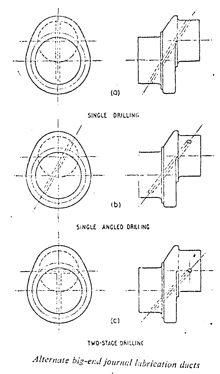
Fig 1.
“The centrifugal pressures can have an important influence on the flow of lubricant to the various crankshaft bearings and may lead to actual starvation at high speeds when there is some wear in the bearings. Consequently the small reduction achieved by the angled drilling (Fig. 1b) can produce a useful gain in this respect.
“It will be noted from figure 2 that the effective radius on the con-rod side, and hence centrifugal pressure, has been reduced. A further reduction of course is achieved by the cross-drilling shown in Fig.1c, although this operation adds a further drilling operation to the manufacturing process and thus incurs a small cost penalty.
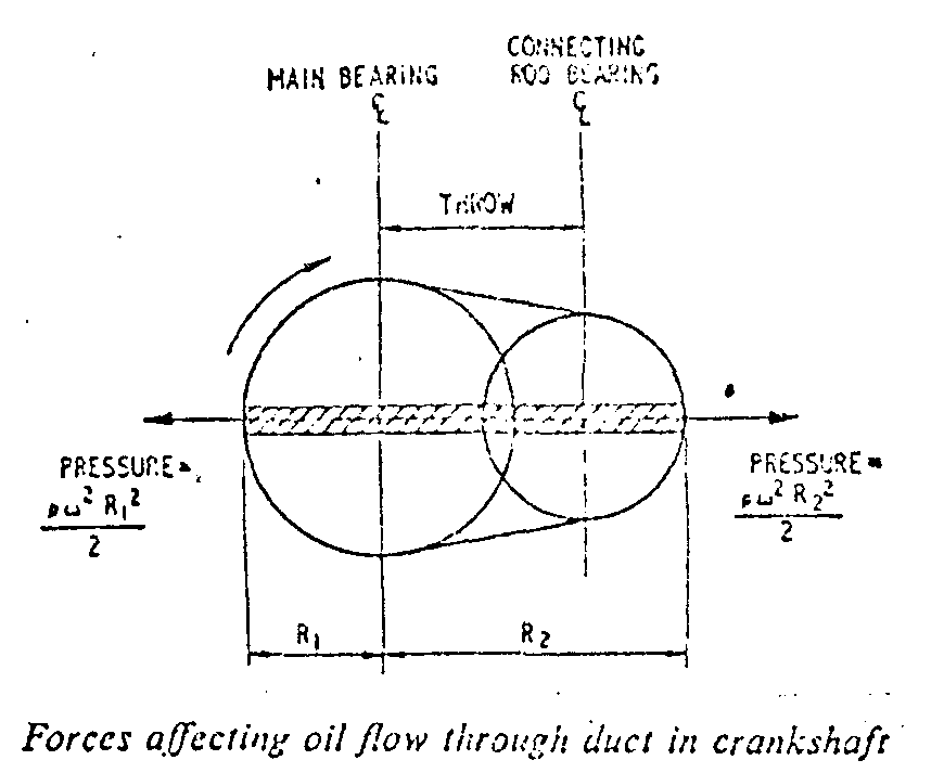
FIGURE 2a
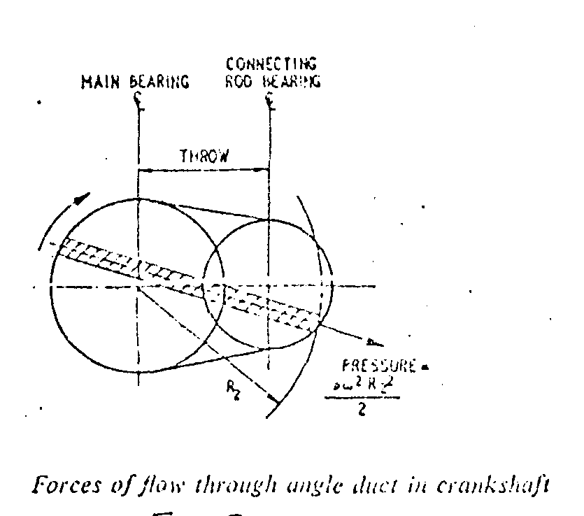
Figure2b
“This has extra advantages of:
1. Oil feed to journal at two positions;
2. Oil holes positioned where minimum load occurs;
3. Inertia force on oil is not increased by an increase in con-rod journal diameter; and
4. Oil flow is not biased towards one side of bearing as is evident in methods a and b.”
The reader will digest all this and say well this is very nice but what can I do to incorporate all this theory into my rebuilt 1994 Javelin. The answer with the crankshaft theory is, very little, but maybe we can do something to the bearings.
To get an idea of what has been achieved we need to look at racing engines and the other similar engine to the Javelin, the VW. Firstly, it is standard practice in Lotus Cortinas and other similar engines to replace the main bearing shells with a full oil groove all around, with a pair, one of which is plain and the other with a groove. This reduces the supply of oil to the big ends to half the crank revolution and retains it in the mains which seemingly is adequate! Racing “Minis” sometimes reaching 9000rpm, according to Mr. Ted Thompson (balance expert from Kumea), sometimes have bronze plugs with smaller cross holes in them fitted to the cross—drillings of the cranks which feed the big-ends, again the purpose of which is to restrict the oil flow to the big-ends which is adequate at high revs due to centrifugal force anyway. And, of course, the VW which is very similar to the Javelin engine was, in the early sixties, having the same troubles with centre main bearings wearing out for exactly the same reasons, albeit ten years later because of the unstressed nature of the VW engine. Their solution was to fit a completely plain bearing shell in both halves (the front and rear were made in one piece and pressed into the block). For the centre the shaft had a small groove ground into it for about half an inch around the circumference area in line with the hole, giving a squirt of oil each time the groove passed the holes.
So here we have some solutions to the centrifugal problem, but which is the easiest (and cheapest) way of applying this to the Javelin. Well, as the crankshaft is nitrided (case-hardened) and hard, it is probably best to leave well alone; the plug idea did not appeal due to balancing problems. This left the main bearings, which as the originals had a much-reduced surface area due to the one-third groove, to be improved. A search of the bearing manual shows that the Perkins three-cylinder diesel engine as fitted to the K135 Massey-Ferguson tractor (and numerous other vehicles) had a big-end shell of the same dimensions as the Javelin main. How convenient! A three cylinder too, giving a box with three pairs of shells, in aluminium too!! So we machine the shells. Not as the Lotus, because it is an in-line engine, so we put a small groove from the oil-hole to the join which, in a Javelin, is vertical. This is ideal because in a flat engine the load is at the centre of the shell. In an in-line engine it is at the bottom so a plain shell can be fitted to the bottom half and a grooved one to the top half of the main. We can go one better too, by fitting three sets of shell bearings throughout the mains and fitting some thrust washers to the rear faces of the rear bearing. Again consulting the bearing book, we find that almost all standard thrust washers are .093” thick. Oh well, we shall have to machine the block somehow! Well, so much for theory, let’s put it into practice.
We shall start with the crankshaft. Pick one that will stand grinding and take it to your local engine reconditioner who works with VW crankshafts (ask around as the VW shaft is nitrided, of similar shape to the Javelin and requires the same 3/32” radius on journal corners.) Most reconditioners who do these regularly will have a special wheel which they fit to their grinding machines for which they charge a little extra. Get the shaft ground to one of the following sizes depending on the shaft.
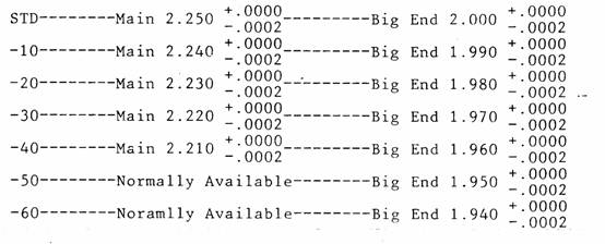
Ensure that bearings of sizes for —40, —50 and —60 can be obtained before grinding. (Available N.Z. Jowett Spares, Ex—Stock.)
Then purchase your bearings for Javelin mains from your Perkins agent, asking for big-end shells for either P3-144 (2.36 litres) or 3-152 or #A—152 (2½ litres), or your Massey Ferguson agent, asking for one set of big-end shells for the K-135 tractor, Part No.85036. Incidentally, these bearings may carry the A.C.L. mark 1012AL (Glacier GS8955 SA in U.K.) on them as they are manufactured in Australia by A.C.L. and packed for the respective suppliers. Also it is worth mentioning here that these bearings are a plain shell for the big ends of a three-cylinder diesel engine. Perkins also happen to make a four-cylinder engine with the same physical dimensions though there are more cylinders; but the three cylinder engine suits our purpose best as it supplies three pairs of bearings which is the right number for the three mains of the Javelin. These bearings now need to be modified to fit the Javelin block as follows:
Original 1978 diagram.
STEP 1: File the tabs off the bearings so that the outer edge of the shell is flush. Some at this point may ask why not use them but if you think about the way the Javelin block was made it will be clear. The two halves were bolted together and the whole block bored as one piece. Thus the centre line of the block may not coincide with the centre of the bearing and, if one half circle is smaller than the other, the shell would not fit. So by putting a dowel at right angles to the join the bearings will fit and will not spin in the block.
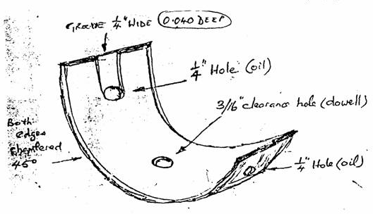
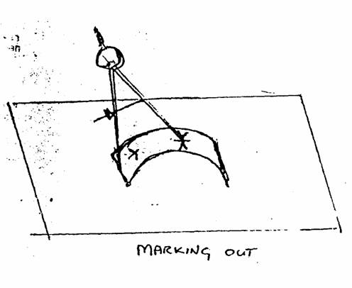
STEP 2: Mark out the three holes per shell as follows: take a pair of dividers and placing the shell on a flat surface scribe a half line from each join side to find the centre of the outside, Then, taking an old shell, mark off it the two oil-supply holes in roughly the same position. Then from each edge mark the three holes on the centre line.
STEP 3: Centre pop and drill them with dowel hole having a clearance of 3/16” (I use a No.11 drill) and the oil supply slot being 6mm. De-burr the holes after drilling.
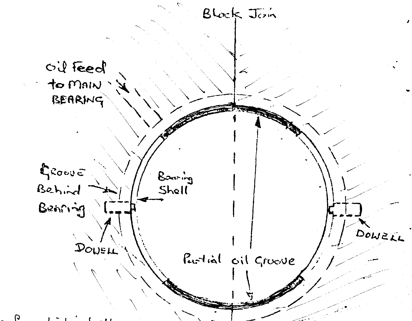
STEP 4: The groove is the crux of the bearing machining — and will depend on the model of block you are to use for your engine. Bearing in mind the preamble about oil flow and centrifugal force and so on, I have concluded the easiest method of obtaining the desired effect from the various alternatives is to modify the bearings. Now, if the block is an early PA, PB or PC, it will have no oil groove machined behind where the bearing shell fits, if it is a later PC model it will have the centre main housing grooved only. If it is a PD or PE block it will have all three housings machined with a groove.
Taking the PA, PB and early PC: A thin groove will need to be machined around all bearings approximately .040” deep and no more than 1/8” wide.
Taking the later PC: the front and rear bearings will need to be machined as above but the centre main will be machined differently as follows (remember it feeds two big-ends).
Updated diagram 2005.
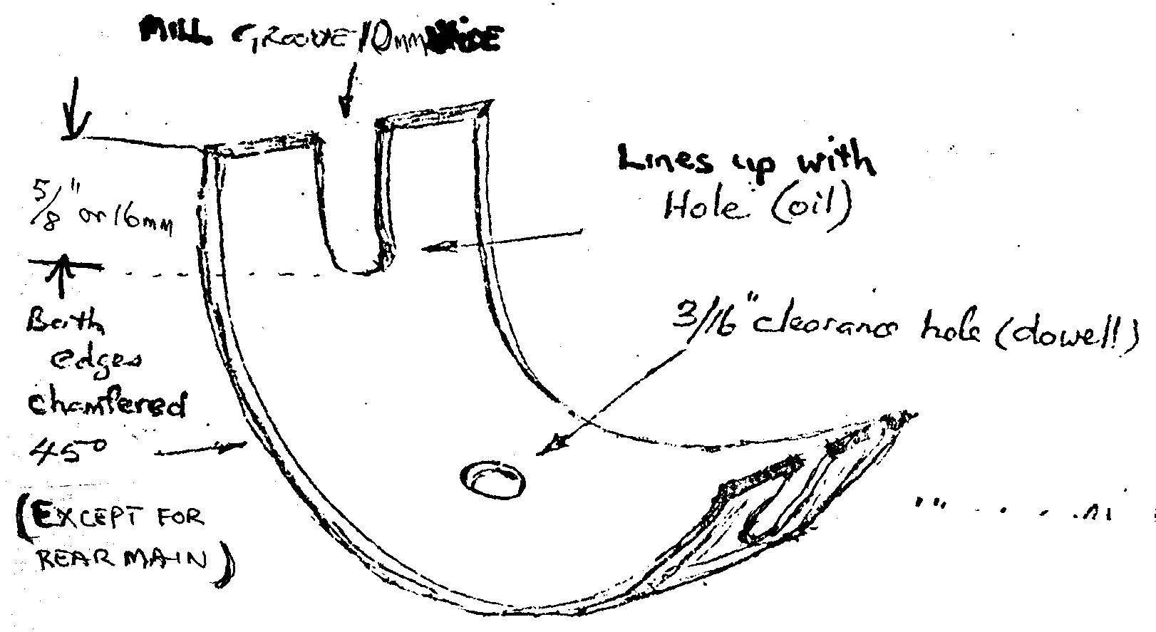
Taking the later PC, PD and PE: See updated diagram 2005 above, machine a groove from the oil holes to the join line of the bearing. This can be done with a milling machine. When the two bearing halves are held together the grooves will join oil hole to oil-hole across-top and bottom (low loading area) of the bearing.
STEP 5: Bevel the edges of the shells at 45 degrees as they are a fraction wider than the originals shell and may foul the large radius on the corners of the shaft journals — front and centre only.
STEP 6: Check shells for any burrs caused by drilling or machining and remove same, clean shell and fit. NOTE: The dowel holes could want slotting with a file a little one side to ensure no binding.
It will be obvious that the PD and PE blocks with three grooves behind the bearings will give the best results and the earlier blocks will only be a compromise. However, if the re-builder desires a PE result from a PA or PB block, the answer is to machine the block with a groove on all three bearing housings. This can be done without removing the dowels by machining a groove slightly to one side of the dowel and making a shallow dent with a grindstone or burr in a drill to mate up with the oil holes, or the dowels can be removed by a needlepoint grease gun and the block machined as per the PE block.
Now for the Javelin big end shells. There are two alternatives. The A.C.L. 2411AL (Glacier GS 8899SA in U.K. and Avenger 264 AL) shell is available from Perkins dealers as a big-end shell for the four-cylinder 1.62 litre diesel engine and the four-cylinder 1.76 litre diesel and require a slight chamfer off the edges to stop the corners fouling on the big-end journal radius of the crank. NOTE: The tabs may need to be filed if the Javelin con-rods have narrow tab grooves.
The second alternative is the A.C.L. 4B2611AL for the Hillman Minx and Superminx 1592cc (1962—65), or the Humber Sceptre and Vogue 1592cc (1963—66) available most parts suppliers. These bearings are .040” narrower than the original Jowett bearings but have been used success fully for a number of years. This paragraph obsolete in 2006.
The tabs also may need to be filed to suit the con-rod tabs to fit the bearing midway. Both these bearing shells will NOT fit straight into the Jowett Javelin without any modification apart from the tabs. Tunnel needs honing by 0.001inch!!
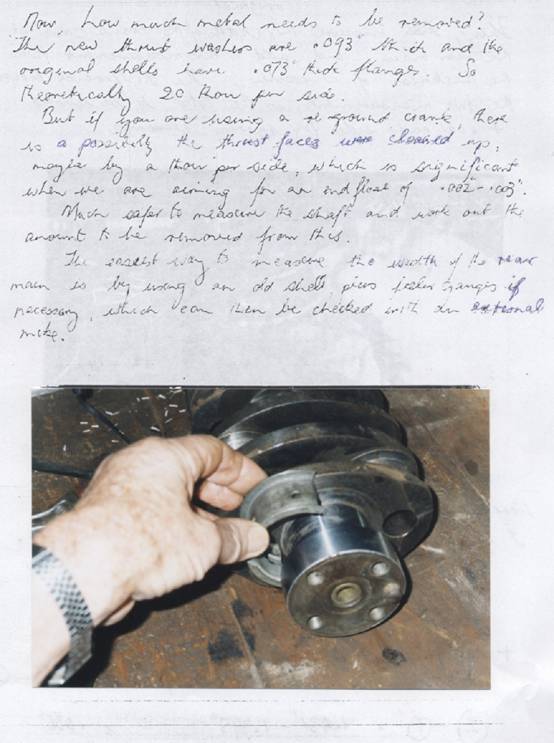
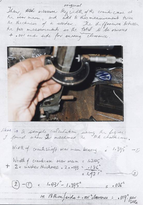
The next stage to be discussed is the fitting of the rear thrust washers. First purchase your thrusts for Mk 1 Consul (1950—55) or Mk 1 Zephyr Zodiac Mkl (1950—55, Repco Part No.213188 (Glacier W2058)or Humber80 thrusts two sets 2.475x3.157inch IT2612. Now because these thrust washers are .093” thick and the original Javelin rear thrust was only .073” thick, .020” will have to be machined off the block on each side. (I have tried to reduce the thrust washer but it is not successful and very time consuming, resulting in a non-standard job anyway. It is better to machine the block and be done with it as replacing the thrusts is relatively simple next time).
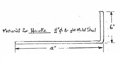
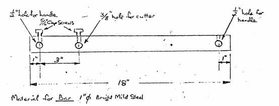
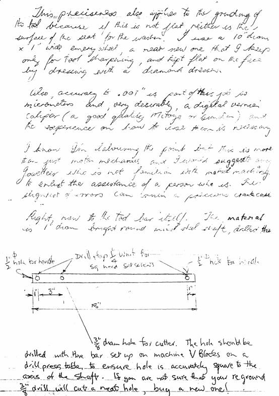
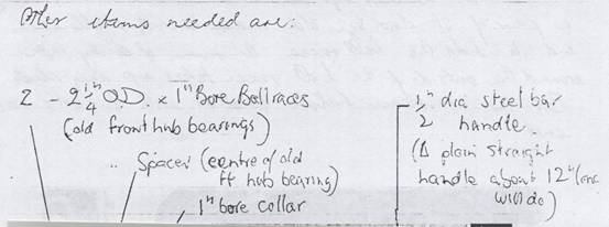
I have made up a special tool for machining the rear bearing by hand using simple gear. For details see sketch. The extras to be purchased are:
2 off Sealed bearings, SKF RLS8 or equivalent Hoffman LS1O
2 pairs of old standard Javelin front or centre main bearings.
3 off 5/16” Whit. or SAE, 3/4” long cap screws and taps to suit
1 length of 1” dia. BMS 19” long
1 length ½” dia. BMS 18” long
1 piece of 3/8” dia tool steel HSS
1 1” bore mild steel collar with cap screw
1 centre out of an old front wheel bearing as a spacer
1 set of feeler gauges
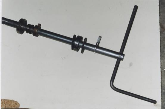
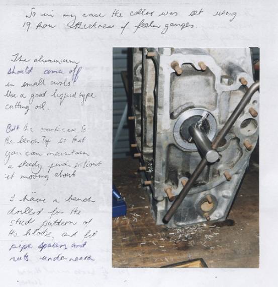
1. The tool steel is sharpened for about 1” of its length by being ground flat to the halfway line, taking care not to overheat when grinding. A light hone with an Oilstone will give a good cutting edge on either side.
2. The 1” bar is drilled as per drawing.
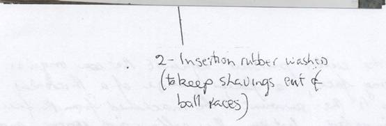
3. The ½” bar is bent with a 6” handle
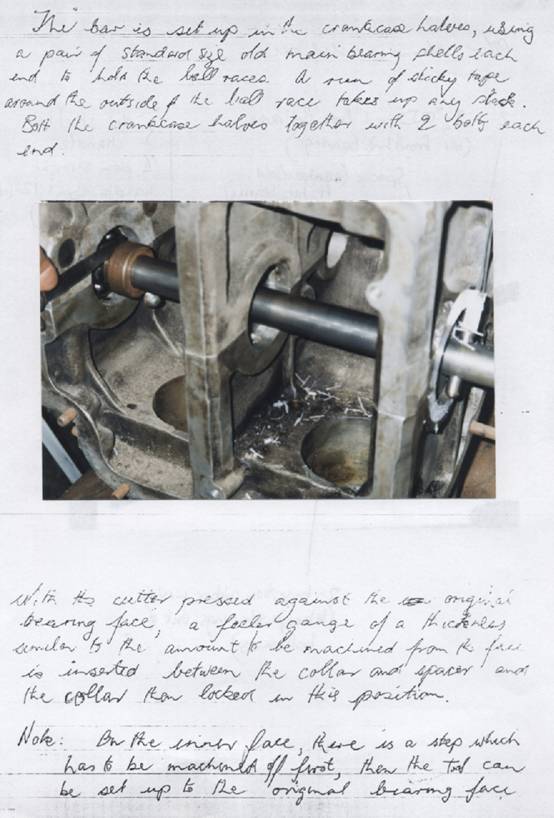
4. The old bearing shells will be set in the block with a piece of Cellotape to take up clearance F and R bearings.
5. The ball races will sit on the shells and the block halves are bolted together with four bolts, two front, two rear, to hold the bearings nipped.
6. Then the bar will slide through the bearings.
7. The cutter blade is fixed by a cap screw in the bar at right angles to the face to be cut.
8. The spacer and collar are slid on the bar against the bearing centre, the outside end, and with the handle inserted at the opposite end to the cutter blade.
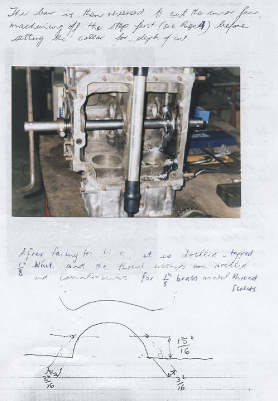
9. The collar is set with the cutter blade pressed against the block and a .020” feeler gauge is place between the collar and the spacer. The collar is set and locked with a cap screw. The cut is set and may now take place by turning the handle and l’ a moderate pressure on the bar until the collar sits on the bearing spacer and the .020” has been cut off. The aluminium cuts quite easily and smoothly with moderate pressure. The process is then reversed by putting the cutter blade on the other side of the block, changing the handle to the other end and setting the collar gap again.
NOTE: The only point to watch is that on the inner face of most blocks there is a partly machined step where the original bearing sat. The higher portion requires to be carefully cut down to the original bearing level and then the .020” removed from the face.
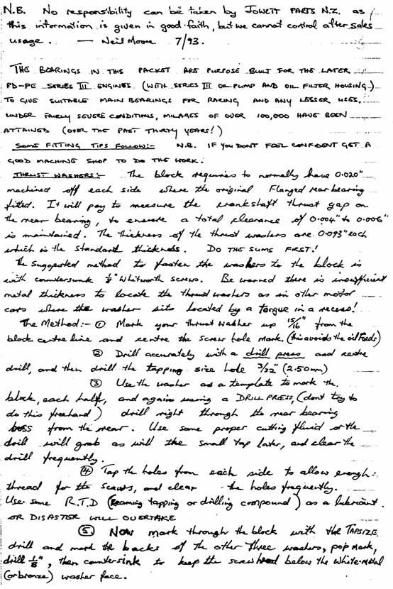
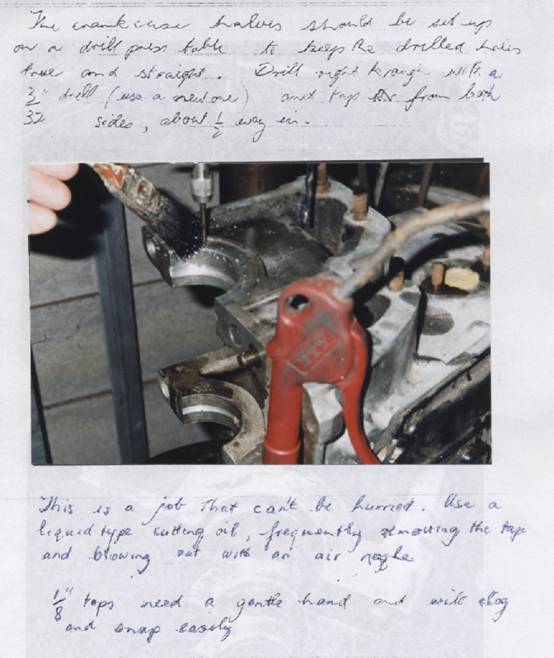
Next is the job of drilling and tapping the block for the thrust washers.
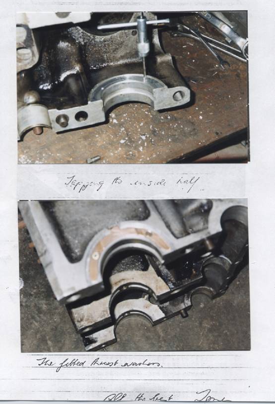
STEP 1: With the blocks still bolted mark out the holes for screwing the thrust washers to the block as follows: scribe a line 15/16” in from the join parallel with the join both sides. Then mark 3/16” in from the curve face of the bearing housing. Centre pop where the lines cross. This misses the oil feed. It is better to drill the thrust washers 15/16inch up with tap drill size and use these as a jig to spot holes on block for drilling! Then using drill press, drill right through the block rear face slowly, clearing the drill often!!! Then tap each side deep enough for 3/8 or 1/2 inch long countersunk screws.
STEP 2: Using a drill stand (It is essential that the holes are square and straight) with a 3/32” drill, centre—drill the four holes and then drill RIGHT THROUGH the rear housing.
STEP 3: Now tap the holes with 1/8” Whitworth taps halfway in from each side, frequently clearing tap. NOTE: It is essential that a tapping lubricant be used on the tap in aluminium or a broken tap will certainly result. The best is ROCOL RTD compound (which stands for Reaming Tapping Drilling). Next best is neatsfoot oil or kerosene.
STEP 4: Taking the thrust washers mark the back of them with a felt pen and then put on the block in place and mark through with the 3/32” drill from the other side of the hole. Mark the place of each thrust washer to the block so they do not get mixed and then drill the washers 1/8” and countersink for 1/8” Whitworth countersunk BRASS machine screws 1/2” long. Make sure the countersink is sufficient for the screw head to be well below the surface of the thrust washer. It may be necessary to lightly countersink the tapped hole entry into the block to allow the washer to sit snug.
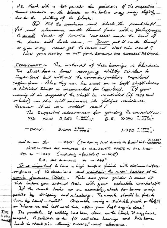
STEP 5: The washers can now be fitted and screws tightened. The crank shaft can now be assembled and when finally torque to 70 ft/lb the crankshaft should be able to be turned by hand without a flywheel or spanner. If not, strip apart and check for high spots where the shaft may be binding. The maxim I use is: “If it will not turn by hand cold, it will not turn for long hot”.
Thanks to Neil Moore for the above.
Here is the description of
using the crankcase
modification tool by Tony. .
Mods to front (early) susp front.hubs &-crankcase tie-bolts,
I can report that it. hasn’t always been a. case of lazing on the sunny afternoons in the West Oz summer time and that El SA 163R is now showing some progress on the restoration front
The chassis work is now practically complete, just the water pump and dynamo to finish. It has been a typical case of bringing a Jupiter back to life from an incomplete kit of parts; a well known tale so well detailed recently in ‘B-J’on Reg Gilbert’s excellent 4 part account. In fact, I reckon this should be published as a book entitled “Everything you need to know about restoring a Jowett Jupiter”. . . -
I too had the benefit of an old Javelin for the supply of some of those missing parts. It wouldn't be too far out to say that the project would barely be possible without one. There were, so many items that were practically, beyond salvage because of the 14 years or more that the Jupiter had been standing in the open; even the torsion bars were too deeply corroded to re-use. Hence, my restoration narrative closely follows Reg’s; however, a few variations arose , . . ‘‘
After the complete strip down of components remaining on the chassis frame, a scrape and wire brush revealed that the rust pitting of the tubes was quite deep and rather than risk further metal removal and possible holing with sand blasting, I chose to use a rust converter which chemically changes the surface rust and the resulting finish resists further corrosion This was followed. by a zinc primer (cold galvanising)--then two part acrylic urethane enamel primer and black top coats., This looks good and will provide long term protection
The first restored components to be assembled onto this shiny “new’ frame were the front suspension bits, and these are the original SA types; because, as much as I can. I will use what I’ve got and I prefer to keep it that way. So I have not converted to rubber bushes and, between the Jupiter and Javelin parts, I managed to put together a good pair of swivel pin yolks and their threaded pins. Not that this would have been a real problem otherwise., because Tim Kelly, ‘(South Australian Javelin owner) has made a slightly oversize’ tap for cleaning—up these yolk threads and machined 0/S threaded pins to suit. .
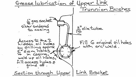
Lubrication of the upper, link trunnion bushes has been changed from oil to grease. NO, not by just screwing’ a grease nipple into the original plug hole, as I’ve found on many Javelins, which firstly proceeds to break off the soldered back plate, then fill up the cross tube with ‘lOlbs of grease before effectively lubricating what it is meant to. The back plate was unsoldered and an internal copper tube fitted from a 1/8”gas socket in the original plug hole directly to the tube holding the bushes, Previous holes in this tube were filled.
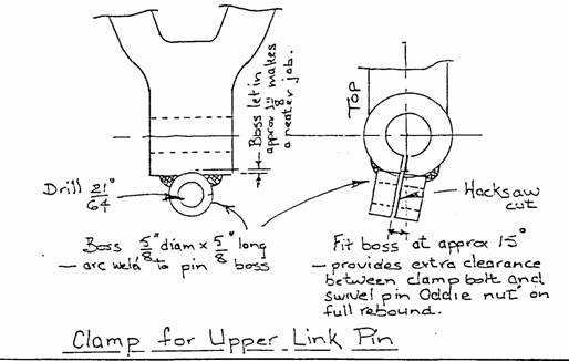
Also, I fitted a clamp bolt to the outer end of the upper link to hold the pin firmly in the boss This really should have been there from the start. Inevitably the pin is going to rotate in the area of least résistance, and in all cases I have seen there has been varying degrees of wear at this point, requiring the boss to be bushed back to ½” bore; usually the pin needs building up as well..
Wear on the rack and pinion was negligible, so it was simply cleaned and reassembled with new rack gaiters and a new sealed type thrust race for the pinion shaft. From my parts, I assembled two very good tie rod ends, the adjustable style as was original eq on this Jupiter. The Jowett universal joint on the steering column was quite worn and, although fixable, I thought a better long term solution was to fit the latter Hardy .Spicer type, This is partly done., now awaiting the refitting of the body to determine exact location.
All the items needed for the rebuilding of the braking system were available locally, apart from the master cylinder kit which I obtained from JCC of Aust, who also had a brand new master cylinder body. Great! The new linings are bonded now, not riveted, to the shoes, The years of standing had corroded the bores of the wheel cylinders and these were stainless sleeved; and the pistons I had re-plated. All steel lines were renewed, using the original flare nuts, and the flexible brake hoses I found here
In fact, I’ve. been pleasantly surprised at the range of parts that I have acquired from local suppliers. All bearings and oil seals - have been no problem, even the circlip—grooved gearbox main shaft races and the tail shaft centre bearing; the stepped housing pinion oil seal and repair kits for the Hardy Spicer universals
Back to the brakes:- I filled the system with silicone brake fluid--- non hydroscopic — so it’s excellent for cars that are not used sufficiently often., to vaporise the moisture absorbed by ordinary fluid. I have had it in the Javelin or the past 5 years without any troubles. . .
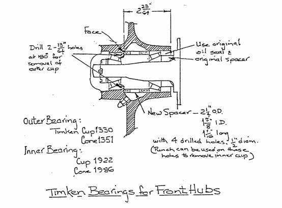
I fitted the front hubs ‘ Timken taper bearings., although not exactly as shown in “B—J No l/87 I used bearings sizes that matched the original—ball race diameters so that there was no machining required on the bearing surfaces. A simple tube, spacer locates inner cup; I faced the rough casting where this spacer sits against the hub. It is a pleasure to be able to delete the threaded ring and satisfactory adjustment of the bearings was obtained with the original castellated nut,
You may remember that the original Jupiter engine did not, come with the car. There were some Javelin engine parts, one 30—VIG—5 Jupiter carburettor, the original air cleaner and oil cooler, I have built up an engine around Javelin crankcase El PC 12871 (production No 13878), with a Laystall crankshaft which happened to be in a burnt-out Javelin that a local JCCA member discovered, This was a great find as Laystalls are very scarce here; not only that, but it was still standard size -and didn’t need regrinding. I also used the con-rods ‘that came with the shaft, and put it all together with the standard shells from the Club spares. ‘
A thing that surprised me in my early studies of these Jowett engines was the omission of positive crankcase dowelling. The factory pegs, because they are fitted to the top half of the cases only, are simply assembly guides and do nothing to hold the two halves across the bearings.
That this is quite necessary has been. shown on all engines I have studied, the matt—grey areas on the mating. surfaces being most noticeable around the centre main. I have since read comments from others with similar views and I recall Ian Dearie also mentioning this point in. an article in ‘Jowett-Sport
Restricting the movement between the cases must extend bearing life and, long term,, the life of the crankshaft.
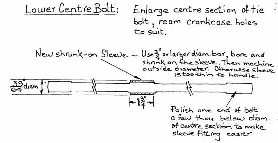
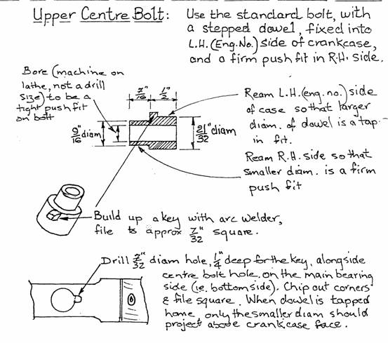
I have never seen drawings of how others do this, however my idea as shown is simple.. I dowelled across the centre main by turning and fitting sleeves for the centre tie bolts, reaming the bolt holes to give a firm push-fit And it works! I first used the system when restoring my Javelin and had reason to inspect this engine a few years later when some work was needed for cylinder head sealing. Evidence of movement was gone, the crankshaft and bearings as new.
There are a few points to explain regarding the sketches:
The key on the upper bolt hole dowel prevents amy possibility of the dowel working down the hole and blanking off the oil feed around the bolt to the centre main
The outside faces of the upper dowel to the locating of the crank case halves, so in theory there is no need for the tie bolt to be a neat fit internally as I have shown. This was done because the dowel wall thickness on the smaller end is only 1/32 and I felt that a solid backing would help. The dowel diameters shown were chosen to allow sufficient for cleaning up the original drilled bolt holes without requiring too much reaming. Excess reaming invites errors
Obviously, the secret of the whole job is precise reaming and that means experience in their use.. Done correctly, the assembly is a tight push-fit and picks up precisely with the two factory pegs
One big bonus amongst the engine bits that came with the Jupiter was a brand new. set of liners, pistons and rings. Very fortunately, these had not been left in the open but were in a shed on the property (together with the one and only instrument that was left - the rev counter).. Not that I realised their new condition at the time, with their covering of dust, leaves and cobwebs. Naturally, these were fitted
Heads are from two Javelins; it is hard to find them here without cracks, the results of overheating in our Summer; as are starter, distributor and all the covers. I found one of the later type Oil pumps with the adjustable relief valve in the engine from a wrecked Javelin, and after soaking and freeing up, it worked well. With the spring setting backed ‘off as far as I’m game to undo, it operating pressure is still 75psi ‘
I found another 30-VIG-5 carburettor at an auto-jumble - not from a Jupiter of course different operating levers and jets.
On my way through Melbourne to the National Jowett rally last June, I was introduced, by former Jupiter owner Ray Isles, to a shop which specialises in carburettors - all sorts and nothing but. Here I found the correct sized jets, new idle screws, over size diameter thrott1e spindles, and all the gaskets. I made throttle and choke spin to the original samples.
A second-hand SU pump of the right type was found locally and coaxed back to life with a new set of points and diaphragm and a Jupiter style L.H. exhaust manifold was manufactured from an Ex. Javelin unit.
Well, does it all work? Yes, indeed, and it’s music to the ears Before installing the engine in the chassis I set it upon my test stand, using an old Javelin radiator and water pump
The first few starts were brief, while I gradually reduced the oil pressure from 100psi - As I mentioned earlier, this is still over. the manual figure of 65-7Opsi, at 75psi on it’s minimum setting but it is early days and the whole unit is quite tight.
Next, the engine refused to run below 1500rpm and pick—up was patchy. Adjustment of idle mixture and throttle stop screws made no difference, so I removed the carbs for a more detailed study. I found firstly that the throttle butterflies were not a precise fit in the bodies, touching one side before closing on the other. The bench was covered with Zenith bits during the carburettor rebuilding saga and obviously I’d got these discs mixed. I went through all my spares and selected two which, when held to the light, showed the, best closure. It is amazing how much variation there is with these,
Also, on close inspection, the throttle lever that I made was just slightly different in its operating angle to the original, the effect of which was to open the throttles at different rates.
And the third discovery was an odd one. The accelerator pump operating lever of my. ‘auto—jumble’ carb was 5/16” shorter than the Jupiter one, producing different discharge rates. Zenith it would appear, made a standard body, then added a variety of levers and controls to suit various engine manufacturers.
This detail synchronising was certainly worth the effort and the engine now really sings. Pickup is now instant and rapid. The acceleration pump remove that slight hesitation and chose glorious, heart—stopping, heaven bound spurts of flame occurring when the throttles are snapped open. Wouldn’t life be dull restoring anything but a Jowett
So, now to the second thrilling episode - the bodywork; and, I think, a somewhat slower stage because I can’t race off to the Javelin spares for those missing bumpers, trim, hood mechanisms, instruments . But I do have waiting, from the much appreciated services’ of JOAC, new hubcaps, door handles, recoated steering wheel and. budget lock covers. Many thanks for all that.